Products
Our Newsletter
The RMGSwitch-BEC is now obsolete. This page is included here for existing users to find the programming instructions and wiring diagram etc.
RMGSwitch BEC special features
- 5 Amp, 6 Volt receiver power supply. details
- Very quick, simple and convenient programming method for ALL SmartWinch models. details
- Replaces both Signal Line Switch and Pulser. details
Features common to RMGSwitch-BEC and RMGSwitch-Std
- Super Low Profile.
- Simple to install.
- LED indicator for system status and intelligent battery voltage display. details
- IP67 (waterproof) very short travel tactile switch.
- Battery supply range from 5 or 6 cells NimH/NiCd or 2 cells LiFe/LiPo.
- Minimum voltage for RMGSwitch operation - 3.8V. Short term fluctuations below 3.8V can be tolerated without unlatching.
- Unlatching voltage - 1.5V. Voltage below this level will cause the RMGSwitch to unlatch requiring a button press to restart.
- Optional fitting of Deans Ultra type connectors (std Deans wiring configuration).
- Dimensions 30mm x 24mm x 35mm.
- weight 30g.
Note that 4 cell NimH/NiCd batteries can not be used to power the RMGSwitch BEC. And while 5 cell NimH/NiCd batteries can be used, 6 cells or 2 cell LiPo are recommended for the RMGSwitch. The receiver voltage will remain at 6V while the actual battery voltage is above 7.2V but will fall below 6V as the battery falls below 7.2. For example, at battery voltage of 6V the receiver supply will be 4.8V. When a 5 cell pack is flat (5.5V) the receiver will only be supplied 4.3V. Most receiver and servos will operate at this lower level but the servos connected to the receiver will be less powerful and slower.
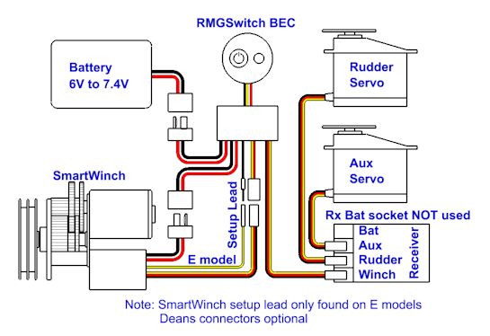
RMGSwitch-BEC connections diagram.
The Aux servo is shown as an example of how the RMGSwitch can supply much higher power to the receiver than the SmartWinch itself can.
The diagram also shows Deans Ultra connectors used for battery and winch connection. These are optional extra which can be specified when ordering.
When used with SmartWinch models without setup lead, leave the protective cover on the switch setup lead.
All connections must be protected against exposure to water.
Do not allow connectors to lay in the bilge of the hull.
Water exposure (salt or fresh) to connectors is the most common mode of failure in the boat's electrics.
Switch Operation, Voltage Display and LED functions.
- To turn the system on requires only a short momentary button press.
- While the system is on the LED will blink once per second.
- To turn the system off, press and hold the button. The LED will light up continuously for 2 seconds. When the LED goes off release the button before it comes back on at 3 seconds to turn the system off.
- While the system is on, the RMGSwitch continuously reads the battery voltage. The lowest voltage read since the last time voltage was displayed is the voltage to be displayed next. This means that the performance of the battery can be monitored over time. It will show the size of voltage drops due to load on the battery by the SmartWinch.
- To display the battery voltage, press the button for less than one second. The LED will then blink the number of Volts. There will then be a one second pause before the number of tenths of a Volt will be blinked. When displaying voltage the blink rate is 3 blinks per second.
The SmartWinch contains a voltage regulator for supply of receiver and rudder servo power. This is 5V at up to 1Amp. This is adequate in most cases but when high power servos are used or multiple servos used then the alternative wiring method must be used so as to increase the power available to the servos. The RMGSwitch-BEC solves this problem by supplying 6V at up to 5Amps to the receiver. It should be noted that for weight saving purposes no heat sink is fitted to the voltage regulator on the RMGSwitch-BEC. This means that while 5Amps can be supplied it is not intended that this be a constant load. When using multiple or high power servos this is not a problem because average current is relatively low. But the RMGSwitch-BEC will have no trouble supplying the peak currents required by high power servos as they demand momentary starting current.
The RMGSwitch-BEC replaces both the Pulser and Signal Line Switch.
The Pulser was originally devised to be used with D model revision 2 winches which would otherwise not work at all with 2.4GHz radios. The Pulser also protects any SmartWinch up to and including D models rev 3 from accidental settings changes due to slow startup of 2.4GHz radios.
The Signal Line Switch was essential for doing setup in C and earlier SmartWinch models with 2.4GHz radios.
SmartWinch Setup Methods using the RMGSwitch-BEC
The simplest SmartWinch setup method ever is the Tx on/off method. However, this method can not be used with many FM radios and almost all 2.4GHz radios. The beauty of the RMGSwitch-BEC method is that it is as easy to perform as the Tx on/off method and it can be used with any SmartWinch and any radio system. It is performed by simply pressing the RMGSwitch-BEC button when required by the instructions. The boat can be completely sealed up when performing setup because there is no need to access the receiver. The only time a hatch may need to be removed is when the drum is below deck and is needed to be removed or fitted during part of the procedure.
RMGSwitch-BEC setup methods
Not sure what model you have? click here