Products
Our Newsletter
A guide to replacing output transistors in D series and earlier circuits.
Recommended Replacements
manufacturer Fairchild Semi
P channel part number FDD6637 (position 2,3)
N channel part number FDD8874 (position 1,4)
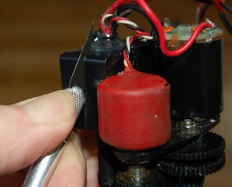
Step 1 Open box
Take great care not to push knife into box further than needed to crack the joint open. Once cracked on 2 sides, box can be pried open with small screwdrive or similar.

Step 2 Remove existing transistors
Use soldering iron to melt the three pads at the same time. Soldering iron should be minimum 60 Watt with fine tip. Use moderate to high heat and extra solder on pads to aid heat transfer.
Drop each transistor one at a time. As the pad joints become molten use only slight force to pull the transistor out. Higer force than necessary may destroy the pads and through hole plating.
Step 3 Clean Pads
Use solder sucker and soldering iron to open pads. No need to clear centre pad.
Step 4 Install New Transistors
Remove both motor leads from PCB. Install first N channel transistor in position shown. The transistors must be placed in the exact orientation as shown in these pictures and in the order N, P, P, N.
Step 5 Finish Installation
Bring N,P pairs together and bridge the tops of the heat sink tabs with the motor leads that were removed from the PCB as shown below.