Products
Our Newsletter
SmartWinch User Guide H series v S8
Most of the information contained here is useful for any SmartWinch model.
For programming travel etc in non G models, please go to the How to Program a SmartWinch page.
1 Introduction
2 Warranty
3 Summary of Features
4 Special SmartWinch Features
5 Power Supply
6 Wiring
7 Standard Connections
8 Alternate Connections
9 Mounting
10 Sheeting
11 Setup (SmartWinch programming)
11.1 Setup Procedure Tx calibration and travel
11.2 Setup Procedure Auxiary settings
12 Maintenance
13 Specifications
The G series models are significant change from the E series.
The potentiometer is replaced with a fully sealed and waterproof 10 turn direct drive Encoder which was developed by RMG Sailwinch.
Models G1 (replaces the 290E1 and 285EF1) and G2 (replaces the 285ES1) have faster gear ratios for the purpose of reducing the loads on the gears. This reduces torque which is compensated for by reducing drum sizes.
The 290G1 model must not use a double spool type drum greater than 26mm or spiral drum greater that 45mm.
The 290G2 model must not use a double spool type drum greater than 32mm or spiral drum greater that 45mm.
The results of the above changes will significantly reduce shock load gear damage while maintaining good speed and sheeting force. The 290G1 is significantly faster than the 285EF1 and about the same speed as the 290E1. The 290G2 is significantly faster than the 285ES1.
-
Warranty period is 12 months from the original end user purchase date.
-
Resale to another end user in the warranty period does not void warranty
-
The evaluation of any claim can only be made by RMG Sailwinch
-
Where no obvious cause of a fault is found then warranty will be assumed
-
The benefit of the doubt will always go to the end user
-
Where there is user damage that is not determined by us to have caused the fault, the warranty will not be voided
-
We make reasonable efforts to seal critical components of the SmartWinch however we cannot guarantee that no moisture ingress will occur.
-
Any fault caused by water voids warranty for the purposes of that fault only
-
Stall protection cannot be guaranteed due to numerous possible causes out of our control. See Stall/Fault Mode on page 2.
-
3.8 to 9-volt operating range
-
Integral 6 Volt 3 Amp BEC for Rx supply
-
Adjustable Tx endpoint limits
-
Adjustable travel
-
Adjustable battery monitoring with low battery shutdown
-
Adjustable failsafe position for low battery shutdown
-
Adjustable input signal deadband
-
Adjustable servo gain
-
Very low on-resistance MOSFET motor drive
-
Stall protection
-
Ball bearing output
![]() 4. Special SmartWinch Features
4. Special SmartWinch Features
Description of Beeps
The SmartWinch uses several sound signals as well as those described in Setup.
Startup beep. A 3 note tune sounds at startup.
Low Battery Warning. 5 rising tone notes at startup indicates the battery is low.
3 beeps per second at startup indicates Setup Lead on Rx ground or signal pin.
1 beep every 3 seconds at startup indicates no command signal input from Rx.
2 notes (high/low) stall signal during normal operation indicates stall or fault.
Stall / Fault mode
The SmartWinch can detect when there is a fault and can protect itself by shutting down. When in stall mode the stall signal will sound at 2-second intervals. This can usually be reset by moving the Tx stick in the opposite direction. If this does not work, turn the winch off and on again. But check for the reason it stalled and resolve it before restarting. Please note that there are several reasons why stall protection may not prevent damage due to overload. These include cyclic overloading where the winch does not come to a complete stall before the commanded position is reached then run back causes the cycle to repeat, inadequate current supply resulting in the winch controller having a “brown out” causing a restart etc. Several factors can result in overheating that stall protection cannot prevent.
Setup Lead
The Setup Lead is a single wire lead with the small connector used to place the winch into Setup Mode for making adjustments. See Setup.
Tx End Point Limits
The SmartWinch samples the Tx endpoints and stores these as input signal limits to prevent unwanted overrun.
Travel Adjustment
Travel can be adjusted between 100 % of maximum down to as low as 20%. The maximum number of turns depends on the model. See Mechanical Specifications.
Battery Monitoring
If supply voltage is below the warning level a warning signal (5 rising tones) will sound as the winch is switched on. If during normal operation the voltage falls below the shutdown level, the winch will drive to the low battery shutdown position and hold there until the battery is replaced or voltage recovers. If the voltage recovers the winch will return to user control. See Table 1 for levels. Default setting is battery monitoring OFF.
What happens if the battery pack size is changed?
If Battery Monitoring is off there are no implications when changing battery pack size. If Battery Monitoring is on then redo Setup 2 Battery Monitoring ON. Changing to a lower voltage battery without redoing Setup 2 will result in a premature shutdown. Changing to a higher voltage pack will result in over discharging the battery if left on till Low Battery Shutdown occurs. Changing battery pack capacity (mAh) has no effect on these settings.
Low Battery Failsafe Position (LBS)
The default low battery failsafe position is booms half out. But this is only true if using a spool type drum. If a spiral drum is used then this position would be closer to full in and could make it difficult to get the boat ashore. To compensate for this the low battery failsafe position is also adjustable so you can choose to make it further out if desired. The range is from half to full travel. This applies if only Battery Monitoring is turned on.
Input Deadband (DB)
Input deadband is the amount dithering in the Rx signal that a servo can tolerate without responding to by constantly jittering. This is adjustable from 0.8 to 10 microseconds. Deadband adjustment allows the optimization of Tx fine trim control. The default setting is 2 microseconds.
Servo Gain (SG)
The rate at which the SmartWinch decelerates from full speed to stop can be adjusted. The default setting is approximately 100 %.
Absolute voltage range is 3.8 to 9 volts. However, the internal BEC for receiver supply requires a minimum of 5V from the battery to supply sufficient voltage for most receivers. Even then, depending on the battery type, this may not be enough. The table below shows various battery types, numbers of cells and capacity recommendations. Power supply connection must be made via the red and black power supply leads and not from the Rx.
Snap-In Battery Holders must not be used. Their weak electrical connections can result in severe voltage drop which causes erratic system behaviour. Battery packs should be fully welded/soldered.
Battery Table. Table 1
| Type | Performance | Number of Cells | Min. Capacity |
| LiPo/LiFe | # # # | 2 | 1000 mAh |
| NiCad | # # N/R | 6 | 1000 mAh |
| NimH | # N/R | 6 | 2000 mAh |
| SLA | # N/R | 6V | 1000 mAh |
N/R = Not Recommended
Battery Monitoring Voltage Levels Table 2
| Level | Battery Pack | Detect | Warn | Shutdown |
| 1 | no longer supported | |||
| 2 | 2 Cell LiFe | <=7.6 | <=5.9 | <=5.5 |
| 3 | 2 Cell LiPo | >7.6 | <=6.7 | <=6.2 |
| 4 | Battery Monitoring turned off | |||
Voltage Regulator (BEC)
The SmartWinch contains a 6 volt, 3 amp BEC to supply to winch controller, radio receiver (Rx) and a standard power rudder servo. The winch motor runs on the full battery voltage via the MOSFET output circuit. Please note that using high power servos for rudder can cause Rx problems.
Supply Leads and Connectors
Wire size from winch supply leads to battery pack must be at least 0.5mm2 (20 AWG) cross section. Switches and connectors used should be rated at least 3 Amps. Standard servo size wiring and connectors are not adequate. It can cause a severe voltage drop between battery and winch and should not be used. Recommended connectors are Deans Ultra, XT60, XT30 etc.
Supply Polarity
Power supply/battery lead connectors must be polarised so that it is impossible to accidentally reverse the supply polarity. The control circuit and radio gear is protected by the BEC and will not be damaged by reverse polarity but the MOSFET output circuit is likely to be seriously damaged.
Servo Connector (Rx Lead)
The connector supplied is compatible with most radio brands such as JR, Futaba, Hitec etc. Take care when inserting the connector into receivers other than JR or Hitec. It is possible to insert the connector the wrong way around in some brands receivers. However, this will not do any harm except that the Rx will not operate
Setup Lead
This single wire lead is used for performing setup. See Setup.
In most cases, the best circuit for system power is as shown below. In this system, there must be no Rx battery connection. Power for Rx is supplied by the winch BEC (6V). The use of switches in either system is optional. The RMGSwitch-Std is shown as an example only.
Click here for use of RMGSwitch-BEC
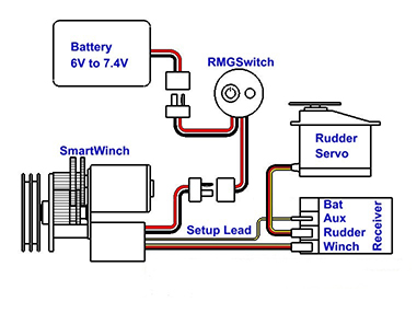
Standard Connections
If a more current than the 3 Amp SmartWinch BEC can supply is required for the Rx or you have 7.4V capable receiver and rudder servo, then you can bypass the winch BEC and power the Rx directly. In this case, the winch to Rx lead red wire must be disconnected.
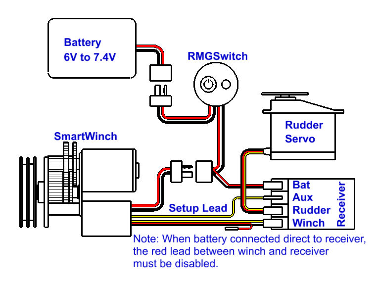
Alternative Connections
Deck Mounting
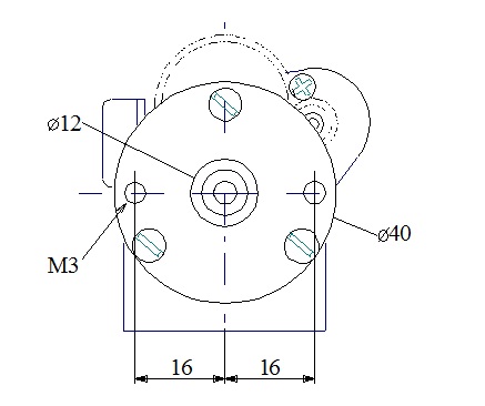
It is recommended to fix the winch to the underside of the deck with drum mounted above deck. Maximum deck thickness is 2.5mm when using the supplied screws. Use csk screws for deck thicknesses above 2.5mm up to a maximum of 4.5mm. Do not use screws longer than those supplied.
Before fixing the winch to the underside of the deck, the mounting face, spigot and "V" ring seal on the shaft immediately below the hexagonal section of the output shaft should be given a liberal coating of Vaseline petroleum jelly or Silicone grease to form a seal. Coat the two M3 mounting screws as well.
Below Deck Mounting
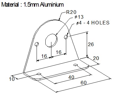
For below deck mounting, it is usually best to mount the winch with shaft horizontally.
Figure 4 shows a suggested bracket for below deck mounting.
Drum Size vs Performance
If faster or slower performance is desired a different drum may be used. Our website has details of several drum options. Using a smaller drum slows sheeting speed and vice versa. However, with a smaller diameter a higher sheeting force is achieved and vice versa.
Sheeting Systems
There are a few different methods that can be used for sheeting on an R/C yacht and no one method can be considered to be "the best way". Two basic categories of sheeting systems used on drum type winches are described below. The purpose in all methods is to keep the load bearing line off the drum from becoming slack.
Single Line With Elastic Tension Line
In this case, only one side of the drum is used and a long elastic line is used to give tension. The elastic line attaches to a fixed point on the boat.
Endless Loop
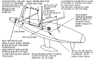
Instead of an elastic tension line, a return line is attached the top side of the drum. As the winch is winding the load bearing line out, a return line is winding in maintaining tension on the load line. As the winch is sheeted in the return line will wind out. Figure 5 is an example of a deck mounted endless loop system.
![]() 11. Setup (SmartWinch programming)
11. Setup (SmartWinch programming)
The SmartWinch has several adjustable features. Adjustments are made by placing the winch in setup mode. Setup is entered by connecting the Setup Lead to a spare signal pin in the Rx. The Setup Lead is the single wire with a small connector.
Figure 6 (below) shows a multi-channel Rx. If using a two-channel Rx the rudder servo lead will need to be removed to access a signal pin. The Setup Lead is shown connected to a signal pin. For normal operation, leave the Setup Lead connected to any spare centre pin (positive). Allowing the lead to dangle free in the bilge is a recipe for corrosion and Setup Lead failure.
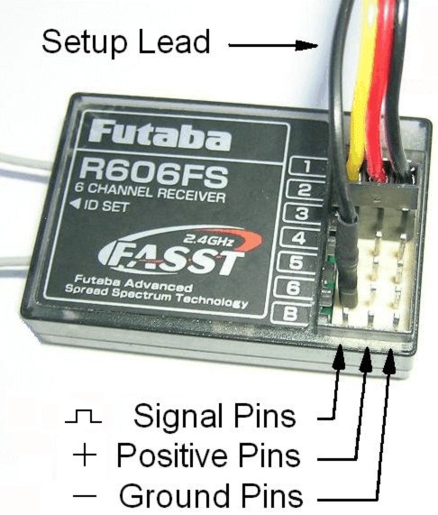
Ground pins are the outside row and are used by the black (or brown) wire of the servo lead.
Positive pins are the centre row (red wire).
Signal pins are the inside row (white or yellow).
The inside row pin of the Rx battery connector is not a signal pin and cannot be used for Setup.
If the Setup Lead is connected to a signal or ground pin when the winch is turned on, there will be a rapidly repeated beep. Reposition it to a centre pin for normal operation.
Setup is not essential to operate the SmartWinch. Travel can be set using a Tx EPA if available. However, this is a powerful servo which can do damage if overrun occurs. Setup 1 is a simple and safe way to adjust travel.
Setup does not correct faults. If the winch has a problem Setup will not solve it. Settings can be overwritten thousands of times so you can experiment with different settings as much as you like.
![]() 11.1 Setup Procedure 1 Tx End Point Limits and Travel
11.1 Setup Procedure 1 Tx End Point Limits and Travel
It is recommended to read through the steps before starting.
- Remove drum if the first time for Setup 1 or after reset done in Setup 2. Turn radio and winch on and check that the winch is responding to the Tx.
- Place Tx stick at full in position and adjust trim all the way in the same direction as the stick.
- Connect Setup Lead to Rx signal pin and wait for a sound signal then immediately move the stick to full out.
About 3 seconds after connection there will be a ringtone like sound signal. About 3 seconds after moving the stick to full out another ring tone will indicate that the Tx endpoints have been saved. The winch cannot move at this time.
- Move stick back to full in and wait for a third long beep.
After the 3rd ringtone, the winch can be driven by the Tx stick.
- Fit drum and manually adjust the lines to set the main boom at full in. Ensure stick remains at close hauled for this step.
- Using the stick, drive the winch out until the booms are at the desired full out position.
The winch will run at a lower speed at this time. Take care not to go too far out as travel is set to maximum at this time.
- With the winch still at the new full out position, remove Setup Lead from Rx.
The SmartWinch will automatically restart with the new settings.
This completes Setup 1. If no more adjustment is required then push the Setup Lead onto a spare centre pin for storage during normal winch use.
Setup 1 Tips
If removed and reinstalled in the same boat with the same Tx or if Rx only is replaced then Setup 1 does not need to be re-done. If the Tx is changed then only Setup 1steps 1 to 3 needs to be redone. If the Tx sail control channel is reversed then Setup 1 steps 1 to 3 must be redone.
Set the booms closer into centre line than normal when setting up at step 4 (but not so tight that the winch is under load). Later when trimming sails for racing the Tx trimmer, EPA or ATL can be used to vary full in sail trim. This will not effect full out position.
If Tx trimmer was left in centre at Step 1 and subsequently moved inward dead stick will occur. It is best to leave Tx trimmer at the minimum for Setup.
![]() 11.2 Setup Procedure 2 Auxiliary Settings
11.2 Setup Procedure 2 Auxiliary Settings
click here for a description of these features.
Note: Setup 1 must have been run previously but does not need to be done each time Setup 2 is run.
It is recommended to read through the steps before starting.
- Turn radio and winch on and make sure the winch is responding to the Tx stick.
- Place Tx stick at the desired position.
For SLT, DB and RMP put the stick at full in for minimum, full out for maximum or an intermediate position as desired.
For LBS, drive boom to desired shutdown position between half way and full out.
For Reset or Battery Monitoring On or OFF the Tx stick position does not matter.
- Push the Setup Lead onto a spare RX signal pin.
About 3 seconds after connection a ringtone like signal will sound. Starting 4 seconds later there will be one beep per second up to 10 beeps.
- Remove the Setup Lead immediately the required number of beeps has sounded. See table 3 below.
If you accidentally pulled the lead out at the wrong number of beeps then just turn winch off now and no changes will be made.
- Hold the Setup Lead onto a signal pin until the startup signal then remove the Setup Lead from the Rx. There is no need to push it completely onto the pin for this step.
The startup signal indicates that the SmartWinch has restarted with the new setting.
This completes Setup 2. If no more Setup is required then push the Setup Lead onto a spare centre pin for storage during normal winch use.
Setup 2 Tips
Setup 2 is locked out until travel (Setup 1) has been set.
For Setup 2, the drum and sheets may be left attached unless performing Reset.
Batteries should be fully charged when setting Battery Monitoring to on to determine the appropriate shutdown level.
If the Setup Lead is removed at 8 or 9 beeps or not removed within 1 second of the 10th beep, the SmartWinch will restart without changing any settings.
If the Setup Lead is removed at 5 beeps, Battery Monitoring On, a number of beeps will be heard indicating the battery monitoring level set. (See Table 2)
| Beeps | Setting |
| 1 | Single-ended Scaled Linear Travel (SLT) |
| 2 | Double ended Scaled Linear Travel (SLT) |
| 3 | Low Battery Shutdown Position (LBS) |
| 4 | Input Signal Deadband (DB) |
| 5 | Battery Monitoring ON |
| 6 | Battery Monitoring OFF |
| 7 | Ramp Rate (RMP) |
| 10 | Reset All settings to default. Drum must be removed first. |
- For the motor, a regular drop or two of light machine oil or CorrosionX to the drive end bushing will keep the motor going for years. Do not allow CorrosionX or any Silicone products come in contact with the motor brushes. It will destroy them. Avoid getting spray on electrical wires or feedback potentiometer and controller enclosure grommet.
- Maintain a coating of white petroleum jelly (Vaseline) or Silicone grease on all electrical connectors inside the yacht to protect against 'black wire' corrosion.
- Regularly re-pack the white petroleum jelly or Silicone grease under the drum of deck mounted winches to protect the ball bearing. Regularly remove the drum and re-coat the area around the shaft and spigot.
- Drain the boat of water as often as required to keep the level of water in the boat to an absolute minimum. After each day of sailing drain boat and leave hatch off to allow the boat to breathe and dry out. This is important for all the boat’s electrics.
- Do not attempt to seal the motor in any way. It must be able to breathe for cooling purposes and also to dry out should moisture get in. It is not possible to seal the motor so any attempt will only make corrosion worse.
- Try to keep gears clean. Greasing is not necessary for Acetal (black plastic) gears. The exception to this is the 380EH. The 380EH metal gears should be greased.